


Panels
We provide integrated products to meet each of our customer's specific needs. The solutions are based on providing leading-edge technology, first quality components and of course following on the customer's specifications.
Accomplishing this mission, UPC counts on close collaboration with the customer in order to finish with a product that reflect exactly the customer's needs. We offer panels for two types of applications like:
- Automatic & Synchronizing Panel for gensets
- Specialized Electrical and Industrial Panels
The panels play an important role giving the power generator installation the needed completeness.
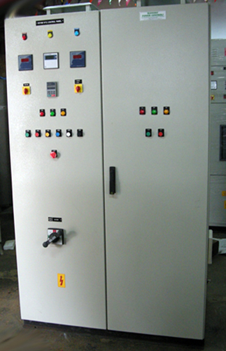
Automatic & Synchronizing Panel for gensets
We are successfully meeting the demands of generator control panels which have high demand among our valued clients for their capability to deliver efficient performance standards. These generator control panel are manufactured using quality materials procured from reliable vendors including switched, aluminium, copper, L angle, CR sheets providing in them optimum functionality standards. We deliver the generator control panels in modular, compact, and rugged construction with fully compartmentalized design options with the following features:
- Auto mains failure DG panels
- Auto synchronizing panel
- Standard DG panel
Specialized Electrical and Industrial Panels
The Panels would be microprocessor based generator set monitoring, metering, protection and control system. It helps us offer advanced levels of functions for reliability and optimum genset performance which is very much important in terms of providing the quality power for use in industries and hospitals.The power command control with digital paralleling control devices are equipped with synchronizers and load sharing controls, and KVAR / Power factor controls.
Presently we are engaged in design, manufacturing & supply and installation of power panels, control panel, feeder pillars etc. Electrical Control Panels that we supply include PLC Panel, AC Drive Panel, DC Drive Panel, LT Panel, PCC/MCC Panel, APFC Panel, AMF Panel, Generator Control Panel.
Needless to say that our panel boards are made under strict supervision by qualified personnel. Our offer on specialized electrical & industrial panels cover the following
Motor Control Center
Motor Control centre both of HT & LT description are on the manufacturing anvil.
LT Panel- Motor Controls centre are manufactured keeping in view of The various types of requirements such as:
- Steel re-rolling Mills
- Paper Mills
- Cement Mills
- Sugar Mills
- General Industrial Workshop.
Steel re-rolling mills, cement mills and sugar mills start on high inertia and as such the starting torque will be high using slip-ring motors. So, we manufacture resistance starters of 3, 5 or 7 steps using either stainless steel grids or Nichrome strips for higher horsepower and ferry or Nichrome wires for lower HP motors. This can be manufactured up to 10 starts per hour and starting torque up to two times the rated torque. The same is manufactured in fully automatic version.
The same could be started using Liquid rotor starter where a stepless acceleration is possible. Here also the starter can be manufactured up to ten starts per hour using forced cooling. Liquid Resistance Starter could also be offered as speed Controls i.e. possible of an Induction Motor. The same could be supplied for voltage from 415V 3P 50 Cys to 11KV 3P 50 Cys.
The protection offered to higher horsepower motors will be in two steps First, the backup CB providing short circuit and earth fault protection and second the motor protection relay giving overload, locked rotor and single phase protections. HT motors are Controlled either by an SFU or ACB for stator Controls (S/C to E/F protection) and a vacuum contactor with motor protection relay operating on this contactor for other protections. HT starters are additionally provided with surge suppressor, PF improvement capacitor also.
These starters could be hooked up to a computer PLC Controls also. The resistance starters for higher starting duties are provided with suitable extra ventilation suited to temperature rise.
The starter when used as speed regulating may need external supercooling in the form of Cooling Towers or Cold Air Circulation.
The client will have to provide the following details while ordering out the units.
| STARTER | VOLTS | V |
|---|---|---|
| Starter | Volts | Amps |
| Rotar | Volts | V |
| Rotar | Current | Amps |
| Connected | Load | in KW/HP |
Type of mechanical load connected or starting torque expressed as a percentage of Full Load Torque, whether used as starter or speed Controllers.
Starting duty : 1 start in two hours | 2 starts per hour | 10 starts per hour
If known mention the accelerating Time. Please note that all high horsepower motors are allowed to start only once in two hours as per Indian standards and British standards.
Not withstanding the above, the starter will be designed to suit the said duties.
General industrial workshops invariably use cage motors in exception to high horsepower compressors and air circulators. Some industries use air circulators with Star-Delta starters by closing the inlet air vent and opening the same after the motor has fully speeded up. Others use slip-ring motors.
Where cage motors are used, the motor is started in three different modes:
- DOL
- Auto Transformer Starter
- Star Delta Starter
DOL: Direct Online Starter
Motors when hooked up to electricity supply authority line is governed by limitations of starting current as the high inrush [say 6-8 times the rated current of the motor] which may affect the co-users of the same transformer by way of Voltage Dips. As such clients are allowed to hook up such motor on DOL only up to 5HP [3.7KW]. Beyond this authorities recommend auto transformer starter. In the Auto Transformer starter, the switching media puts in the motor on a low starting voltage during starting and puts in normal voltage during running. This up to 100HP is allowed for an open transition schedule.
Beyond 100HP korndorfer transmission is designed to take care of close transition. From low voltage to normal voltage connection of the motor. This renders the inrush current on the line to Is/square times of turn's ratio of the Autotransformer over the scheduled DOL inrush. Say if it is used 40% winding during starting the inrush on the main side will be 16% of 6 times the rated current i.e. almost full load current of the motor. Thus both the motor as well as electricity authority’s voltage drop problems are solved at a time. In case of use of 60% tap the current inrush will be 0.36x6=2.16 times the rated current which is much less than star-delta starting.
But after the 100hp open, transition from low to high voltage is not allowed in view of occurrence of Voltage Doubling Effect during transition. For this the close-transition connections [korndorfer for Connection] is being adopted. This could be offered both on HT & LT versions.
But substation owners of adequate capacities could use even high HP motors say [even 800HP] on DOL. [Both HT & LT]
However up to 100HP still Star Delta starters with open transition is adopted generally, in that case Fully Automatic Star Delta Starters are being supplied with suitable SFU/MCCB/MCB/MPCB back up for S/C Protection. Overload protection forms the part of the starter in the form of MPCB/Thermal Overload relay/Motor Protection Relay depending upon necessity.
Star Delta Starters with Close transition through extra resistors are not in practice but can be instituted in special cases.
DC motor Starters: DC series /Compound/Shunt motor starters can be supplied wherever needed.
Wherein details such as :
- Rated Voltage of DC motors
- Rated Full Load Current of DC motors
- Field Current [In case of Shunt motor]
- Field Voltage [In case of Externally Fed Shunt Motor]
- Starting Torque/Full Load Current
- Starting Time –If known
- DC Shunt Motors could be started with motorized dimmer stats also wherever needed in place of motorized or manually regulated resistances. However step selecting resistance during starting can also be provided for on special request (for external power supplied field).
- Cage motors when started with variable Frequency drives can also be supplied with or without incoming/outgoing series reactors with Bypass DOL.FASD Starters. In case of Bypass Starter Provision of total Isolation of VFD on both sides will be made by suitable contactors. The same contactor used in bypass delta connection could also be used for connections in motor in delta for VFD.
- Cage motors when started by Pole Changing device can also be provided in the form of change over pole pickup arrangement with common protection.
- Forward-Reverse Starters can be provided by electrically and mechanically interlocked contactor arrangement by providing protection on common side.
- All the above starters can be made on HT & LT versions
- Synchronous Motors when started as slip-ring motor by the help of Pole Face windings can also be supplied for starting as slip-ring motor and running a synchronous motor by injecting DC to poles.
- After motor speed picks up in this shortened Pole Face winding acts as damper winding.
Starters for such motors could be supplied. Details necessary will be:
| STARTER VOLTS | CYCLES | 3 PHASES |
|---|---|---|
| Starter Current | Amps | |
| Pole Face winding Voltage (RA) | Volts | |
| Pole Face winding Current (RV) | Amps | |
| Field Current | Amps | |
| Field Voltage | Volts | |
| The above Form parts of the MCC hence enumerated. | ||
Power Control Center
These Panels distribute the Transformer /DG supplied Power to various Load Centers Form a Master Controls to such Distribution and Sub- Distribution Board.
Some types of PCC are as:
- Circuit breaker Panel in single or Two tier Formation
- SFU/MCCB’s in multi tier Formation
- Combination of both.
They are provided with suitable mechanically and/ or electrically interlocked to achieve various complicated forms of supplies.
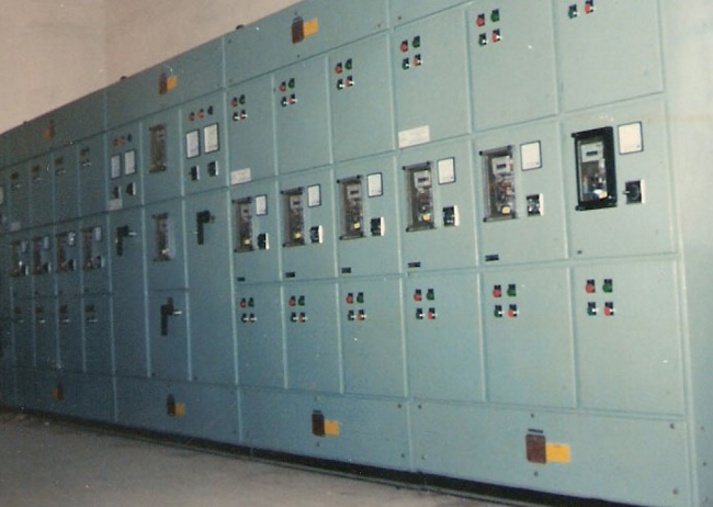
Some types of PCC’s are illustrated in the accompanying photographs. Most important of the lot could be double bus bar panel which is very versatile in the use of DG/EB supply very effectively at will. Such panels can be offered as manually/remote operation by use of motorized changeover switches, electrically operated ACB/MCCB/Contactors. This entire panel uses changeover arrangement for pickup of supply from EB to DG or vice versa. Here some of the load could be running on EB and some on DG at the same time. This may help for specialised Load to run on DG and others on EB. When Power cuts are instituted by electricity authorities such panels help a lot. We manufacture Dupleix and Walk way panels also.
Metering of such panels and feeder interlocking can be done as per customer needs. For Details of Interlocks, we may be personally contacted. Any type Castell Interlock or Rope Type Interlock or Self-Contained Mechanical Interlocks could be instituted.
The mimic diagrams of PCC/MCC could also be developed using Semaphores/lamps. We always use Class 1 CT’s for metering with adequate VA capacity depending upon the meters put in series. We use 5P10 or 10P10 CT’s for protection of relays. Where restricted Earth Fault or Differential Relays are concerned, we use Class PS CT’s wherein mention of knee point voltage and the no load current at knee point voltage will become mandatory.
Controls Panels
Controls and Relay Panels for use on 66KV, 110KV, 220KV and 400 KV circuit breakers are manufactured as per customer’s specific requirements.
Controls Panels for special applications in cement mills can be supplied with due interlock for the flow of materials such as Tripping of the supply of material on main side feeder to stop material clogging can be supplied.
Kiln Controls Panels with heat sensing probes, meters and trip Controls can be provided.
Lightning arrestor and Voltage Transformers for use in generating station can be supplied for both HT & LT requirements.
Neutral grounding resistor panel can be supplied as required for generator and special transformer earthing with proper isolation facility.
Turbine Auxiliary Controls Panel to specific requirements can be supplied.
LT Distribution Panel of various varieties as required by customer can be supplied.
Auto Synchronizing Panel with Load Sharing and AMF arrangement can be designed and supplied using various relays available. In this case manual synchronisation provision is mandatory. Neutral isolation by the way of neutral contactor is also mandatory.
Panels using ACB’s for incomers and Bus Couplers with suitable interlocks can be supplied. This is done both on HT & LT.
Other products we manufacture are:
- Metering Panels for multi storied Buildings
- Capacitor Controls Panel for Both HT & LT
- LT & HT Isolated/non-isolated, Outdoor or Indoor bus ducts can be supplied in the standard format. [we do not manufacture sandwich bus ducts]
- Soft Starters in place of Conventional Contactor starters can be supplied.
- Controls Desks as well as PLC aided Controls arrangement can be given.
- HT & LT metering cubicles to electricity authority requirement.
These are elaborated elsewhere
All the above enumerated items are supported by photographs in the following pages with short notes.
Indoor & Outdoor Bus Ducts
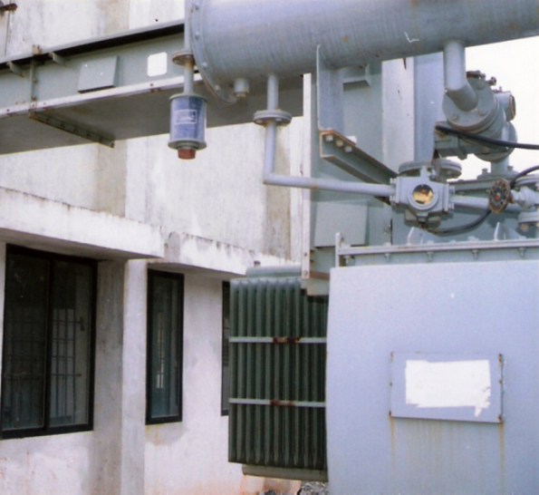 Along side we find a connected outdoor type bus duct in the field. We have designed and erected the same.TPN bus duct and TP bus ducts are designed by us in the conventional fashion for LT and HT bus ducts. We manufacture segregated or non segregated bus ducts both on HT and LT versions. For outdoor use a, hood is provided outdoor bus ducts are specially treated for atmospheric hazards and enclosure designed for outdoor use. We manufacture both aluminium and copper bus ducts. Generally we use a 14 SWG ms sheet for enclosure the design is generally for 50KA for 1 minute. However this does not apply to bus raises. We supply and erect (our bus ducts) bus ducts by suitable designed supports.
We don’t manufacture sandwich bus ducts.
End connection in the form of flexible copper or aluminium strips or copper braided tape can be supplied with bus ducts when needed.
End bellow type bus enclosure could also be supplied in special cases.
Our design does not need a bend or t-joint. However if needed they can also be supplied.
Adopter boxes both at panel and/or transformer end can be supplied.
Two tier Air Circuit Breaker Panel
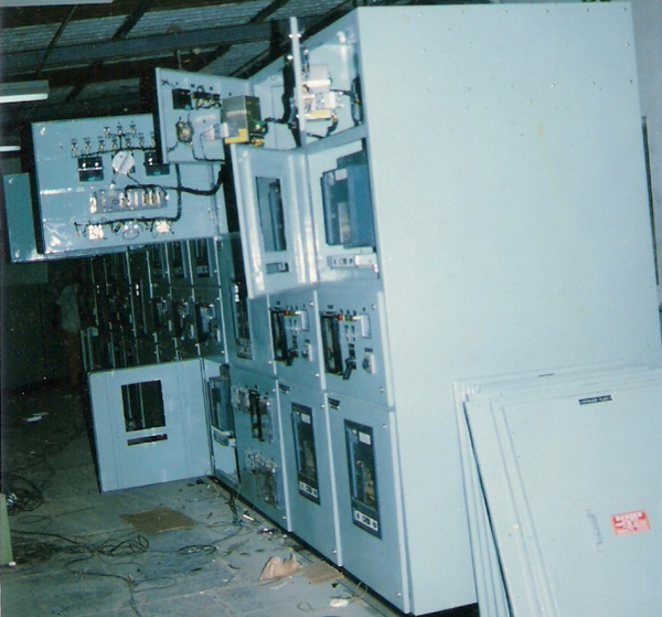
The above panel illustrates a two tier ACB panel where in two ACB’s are arranged one above the other. Wherever accommodation space for panels is a problem, such arrangement is sought for. However multistoried arrangement for FSU/MCCB is always a practice. One can see relays and meters fixed on this panel. Any type of protection suitable can be given.
Double Bus Bar Local Remote Control Change Over Panel
 Please find along side a change over panel with 2 incomers. Double bus bar and a contactor line up in two rows picking up EB and DG supplies to feed common point load individually.
Two rows of contactors one for EB and another one for DG are available with auto manual selection individually. An auto and man changeover from EB to DG is possible. On manual push buttons Controls can be had both locally or remote Controlled contactors are rated to the full capacity of the feeders.
Today change over load break switches or change over load break FSUS are available. Duly motorized for remote operation. The same type of operation as described above is possible on this system. This workout betters on higher current change over feeders
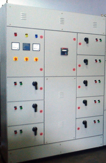
Double Bus Bar Panel
The side panel illustrates a double bus bar panel generally one designated for electricity authority supplies and the other for the in house generator supplies. The above panel has an ACB incomer and interlocked contactor selection of the bus (DG or EB) having the common end supplying the load. The very special feature of a double bus bar arrangement is to use electrical authority supply and generator at the same time. This helps in putting certain special machines' on DG and the others to run on general supply. The bus could be supplied by one or more generators either synchronised or segregated by bus couplers. Though this system is quite costly wherever uninterrupted supply is needed this system scores.
This uses manual changeover switches or MCCB/ACB combinations to select buses. These change over though are manual, can be offered as remote Controls also.
Automatic Capacitor Control Panels
 Capacitors are used in general electrical usage to improve system power factor. Usage of elements like motor in electrical circuit contributes to pull down power factor resulting in drawing higher currents to the same power as 3 E1.cos . Voltage of the system remaining constant at low power factor current being inversely proportional to the same. The current would increase this demands a higher size cable, more voltage drop and loss of energy too.
Most important to the electricity authority is the voltage drop. When a common transformer is used by number of clients, they are interested in the electrical well being of all users on the same transformer. Hence when voltage drops due to high current, It affects the neighboring above and hence they insist upon 0.9 PF to be maintained so that any one person do not contribute to this trouble.
Hence electricity authority insists upon the use of 33% capacitor on the particular transformer used when the customer owns the transformer. Hence say for 1000 KVA transformer installation of 350 KVAr capacitor becomes mandatory. But this is not the end of it. Even after this installation the power factor of the system goes down. It is up to the user to bring up the system PF to 0.9 by use of additional capacitor, the quantity of which could be decided with the knowledge of present PF value the desired PF value. PF penalty will be levied by supply authority if lower PF than 0.9 is observed on the system as well it may lead to disconnection of the system.
Originally use of capacitors with use of a number of switches, switched on/off manually for purpose was used. But with fast load value changing in the system such manual arrangement becomes tedious. Hence automatic power factor correction relays have come to vogue by which step selection becomes fully automatic.
We have got up to 14 step relays which could be efficiently used to suit our requirements. A main line CT and main line voltage is sampled out to operate this relay. Hence an additional CL’s CT’s would be needed in the main panel for the relay operation.
Tapped CT’s could be used in place of normal CT where load has not developed and after the load is developed lower tap could be shifted to the full value. This is view of the fact that the relays need 10-15% of total load current as a minimum for operation.
Wherever transformers are used idle for a length of time in the day the following float capacitor advised to be used to compliment no load loses of the transformer.
- Up to 315 KVA – 5% of transformer KVA
- Up to 1000 KVA – 6% of transformer KVA
- Above 1000 KVA – 8% of transformer KVA
Since this does not fall as a load to APFCR separate capacitor kept floating is necessary. These however add on to APFCR during load running.
Capacitor usage on HT can also be undertaken. They will be outdoor unit without APFCR unit. Now a Days HT contactors are available, Hence APFCR will be delayed switching also can be installed.
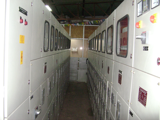
Motor Control Center
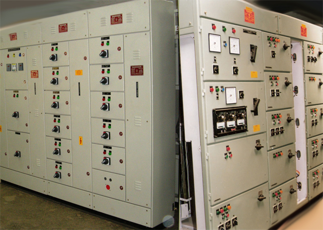 The panel is typical motor Controls centre using one incomer with protections. Metering and status indication lamps.
One can see number of starters (DOL or FASD, VFD, soft starters) arranged in individual or multi storied compartments. The particular panel is built for cement factory with sequential interlock for each starter. That means if any motor in the middle of process manufacturing schedule fails, all the upstream clogging of material in the process stream will be avoided by tripping the up stream starters.
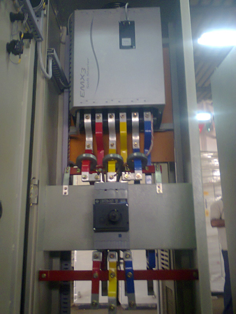
VFD with Bypass FASD Starter

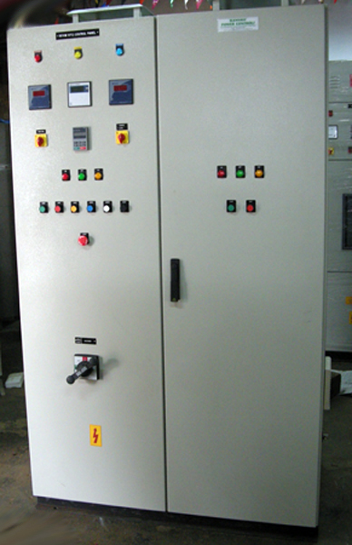
The above panel illustrates a typical VFD panel with by pass arrangement. VFD starters are bought out for which by pass arrangement with auto isolation of the VFD is done.
VFD’s are bought out and connected to series reactors on both incoming and outgoing side or on the outgoing side (as needed by customer) are connected through incoming and outgoing contractor to the system and motor respectively. The major problem in this case is arrangement of a bypass system. In the bypass system say an FASD bypass, in addition to the input and output contactors of the VFD, a full 3 contactor FASD with timer and overload tripping facilities are provided. Please note that the delta contactor in this system will be used both for VFD and bypass starter.
Please note that all the input, output and bypass are fully rated contactors suited or the capacity of motor. Suitable circuit adoptions are done to achieve results.
The soft starter bypass is also very similar to the VFD by pass. However choices of reactors are left the customers.
The VFD itself uses the fact that the induction motor is frequency dependent and the voltages depend on frequency hence any other switch is media not needed for the VFD itself.
VFD with Bypass DOL Starter

The above panel illustrates a typical VFD panel with by pass arrangement. VFD starters are bought out for which by pass arrangement with auto isolation of the VFD is done.
VFD’s are bought out and connected to series reactors either a both incoming and outgoing or on the outgoing side (as needed by customer) are connected through incoming and outgoing contractor to the system and motor respectively. The major problem is this case is arrangement of a bypass system.
In the by – pass system, say a DOL bypass, in addition to two input and output contactors one more by pass contactor is used . The interlock will be such that, the bypass contactor can be switched only when both the incoming and outgoing contactors of the VFD are switched off.
Soft Starter and Bypass Panel
Soft Starters are thyristor based unit used to start Motors. These are generally used on direct online starting or Star delta starting. As a conventional starter of any contactor assembly this also uses three thyristor arrangement for an FASD and one thyristor arrangement for a DOL. All Controls for the thyristors is an inbuilt design of the soft starters.
We provide a bypass either in the form of DOL or FASD as is the requirement to serve the needs of customer when soft starter fails. This bypass arrangement is very similar to by pass arrangement in a VFD panel.
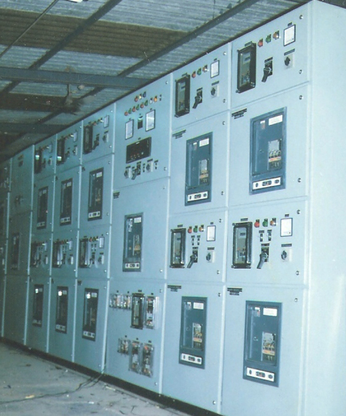
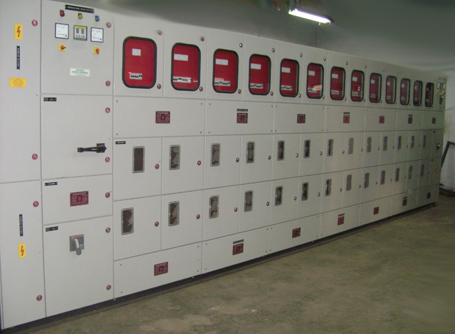
Main Power Distribution Panel
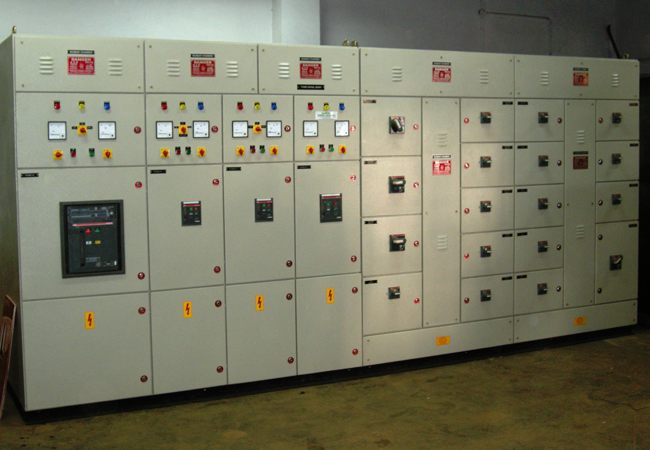 The panel is an illustration of common PCC with an ACB incomer, ACB outgoing as well as some MCCB / SFU outgoing. This illustrates the metering on the major out going feeders.
Multi Storeyed Building Double Front Metering Panel
The above panel illustrates the arrangement of an end use panel for multi-storied building .Here for sub distribution purpose one can see MCB’s are placed in a chamber. Here the individual apartment is supplied with a sealable meter arrangement .This arrangement can be combination of single phase and three phase metering chambers with or without current transformers as per electricity authority requirement.
In some cases automatic changeover from DG to EB and vice versa is instituted by the use of ACCL of suitable capacity.ACCL panel can be supplied as a separate panel also incorporating DG supply in that panel.
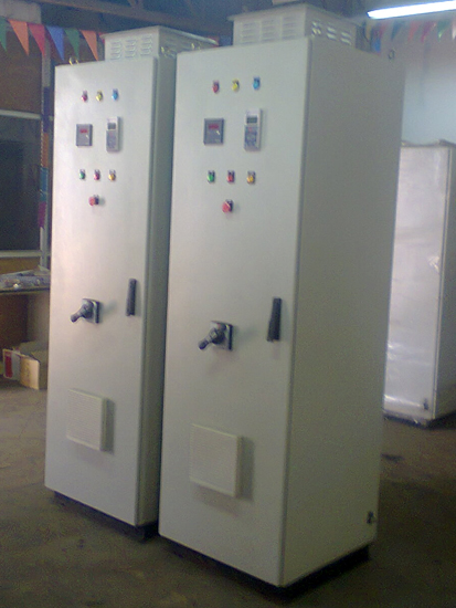
Villas Distribution Feeder Pillar Panel
 Villa distribution feeders derive their supply from the transformers own by electricity authorities. These feeders are generally kept under lock and key. From here individual villas are fed through salable meters kept at the owners premises. The load is connected through ACCL which selects DG or EB supply. These are generally out door panels.
The feeder pillars also contain a loop in loop out system with selection between 2 transformer supplies. So that failure of one supply entails use of the other through a changeover system.